Lesson Guide AD-02
Title: Thrust Sensitive Signal (TSS) system
Ref: NA02B-5DF-6-1 WP 00500
NA01-E2AAA-2-2 WP 071-00, WP 079-00
NA01-E2AAA-1 E2C NATOPS SECTION III
Objective: To familiarize personnel with the operation and troubleshooting of the TSS system.
1. The thrust sensitive signal or autofeather system is a safety feature which will feather any one propeller when engine power loss occurs during take off, landing or bolters, thus limiting drag to that of a feathered propeller reducing the hazards of yawing in multi engine aircraft. The system works automatically in flight, when selected, and acn also be checked on deck with the engines shutdown.
2. The components of the TSS system are:
E. The 75 degree switches, located inside the pedestal, one for each power lever.
F. The autofeather arm switch, located on the pilots eyebrow panel.
G. The two autofeather armed lights on the pilots advisory lights panel below the left windscreen.
3. The TSS system provides a means to feather the propeller in the event of an engine failure.
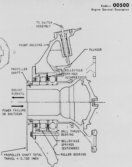
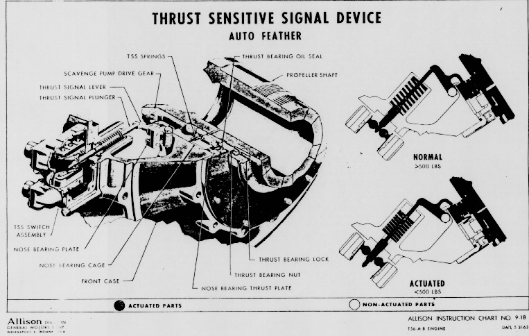
When propeller thrust exceeds 500 pounds the prop pulls forward on its shaft compressing the Belleville springs inside the RGB. If power falls below 500 pounds the spring tension forces the shaft aft, which presses the thrust signal lever to push the plunger out of the gearbox and make contact with the TSS switch. The TSS switch sends an electrical signal to the feather solenoid in the valve hog and to the aux. motor. The feather solenoid inside the valve housing caused the propeller to go straight to feather. When the feather solenoid is positioned to feather the main pump and secondary pumps (which are driven by propeller shaft rotation) combine to send all available fluid flow to the hi pitch line feathering the propeller. The propeller aux. motor which is initiated the same time as the feather solenoid adds its flow to the system to ensure full propeller feather even after the propeller stops rotating.
Three conditions must be met in order to initiate autofeather. 1. The auto feather switch in the cockpit must be armed. 2. The power lever must be at a high power setting of 75 degrees coordinator or above. 3. Propeller thrust must be below 500 pounds. The system has an interlock built in to prevent both propellers from feathering at the same time. The autofeather system is one of the non-committing type so that if propeller thrust increases above 500 pounds before the propeller feathers, the TSS switch opens and the prop returns to normal operation.
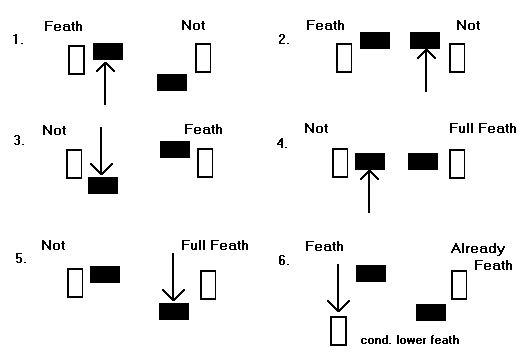
4. The autofeather system can be checked on deck with engines shutdown and is always checked by the pilots before every flight, the autofeather check, simply put, is to make sure both propellers will feather but not at the same time. To make the check:
1. Prop Pump Lights................................................................ON
2. Auto Feather Switch............................................................ON
3. R and L Feather Armed Lights.............................................Illuminated
4. Left Power Lever..................................................................Advance to max power
5. Left Propeller.......................................................................Begin to feather
As the left power lever passes the 75 degree switch in the pedestal the autofeather circuit is complete and the prop should start to feather. Check the PROP MAIN PUMP light is OUT.
6. Right Power Lever...............................................................Advance to max power
7. Right Propeller....................................................................Not feather
The right propeller not feathering indicates the autofeather interlock circuit not functioning.
8. Left Power Lever..................................................................Retard to FLT IDLE
The left propeller motion will stop and the right propeller will start to feather. Check the right PROP MAIN PUMP light OUT and the left PROP MAIN PUMP light illuminated.
9. Left Power Lever..................................................................Advance to max power
Check the right prop continuing toward feather and the left prop static. After right prop has fully feathered.
10. Right Power Lever..............................................................Retard to FLT IDLE
Insure left propeller does not move. This indicates that the autofeather system has been disarmed with one propeller fully feathered.
11. Left Condition Lever..........................................................Feather
12. Left Propeller......................................................................Continue to feather
Observe left NTS light illuminates and R FEATHER ARMED light OUT.
The above steps seem complicated but are actually 6 easy steps hown in the following diagram of the power levers signified by black boxes (filled in) and the condition levers signified by empty boxes.
5. Some suggested troubleshooting procedures for non-operations of the TSS system are:
A. Ensure the autofeather switch is set to armed.
B. Ensure the autofeather circuit breaker is pushed in.
C. Ensure the feather circuit breaker is pushed in.
D. Condition lever feather to see if the aux motor is working and there is enough hydraulic fluid in the prop control.
E. Have the AE’s check the 75 degree switch in the pedestal and the wiring from the TSS switch on the RGB.
Compiled by AD2 R. D. Shuster 15 Nov. 1983